Setup
For circuits without a button: Solder your own switch
Physical connections
- On the circuit you will notice the two leads are labeled "in" and "out."
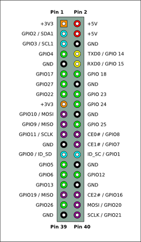
- Using the Pi GPIO header diagram at right, connect the "out" lead to GPIO 23 and "in" lead to GPIO 24. If you prefer to use other pins (e.g. GPIO 5 and 6) simply edit the script as discussed later in the setup. Do not connect to a ground or power GPIO pin. GPIO 0 and 1 can sometimes cause issues as well.
- Connect your original Raspberry Pi power source/micro-USB cable into the micro-USB port on the switch.
For non-direct plug circuits: Connect another micro-USB cable from the circuit's regular USB port to the power port of your Raspberry Pi.
- Press the power button on the circuit and wait for your OS to boot.
Script setup
You can use either keyboard input or SSH to install the script for the switch
If you have a keyboard connected to your Pi then you can type the instructions listed below into the command line and there is no need to use SSH. The Pi must have internet access during installation (but not needed after) for setup. To access command line in RaspBMC, go to the power icon and then select exit and hit the ESC key when the blue screen shows up.
For SSH, recommend using Putty (www.putty.org) or WinSCP (winscp.net), both free.
To SSH into your Pi, find the Pi's IP address provided by your router and enter it in the SSH client (use port 22). Common log-ins are:
- RaspBMC/Raspbian
- user: pi password: raspberry
- OpenELEC
- user: root password: openelec
- Xbian
- user: root password: raspberry
- Arch
- user: root password: root
Installing the script
For RaspBMC/Raspbian/Debian distributions (Xbian as well, omit the word sudo), type the following and hit enter after each line:
1. sudo wget http://files.mausberrycircuits.com/setup.sh
2. sudo bash setup.sh
3. sudo reboot
For OpenELEC:
1. wget http://files.mausberrycircuits.com/setupOE.sh
2. bash setupOE.sh
3. reboot
For Arch:
1. wget http://files.mausberrycircuits.com/setupArch.sh
2. bash setupArch.sh
3. reboot
After the Raspberry Pi has fully rebooted, your switch is now ready for use!
To use a different GPIO pin:
RaspBMC/Raspbian/Debian:
1. sudo nano /etc/switch.sh
OpenELEC:
1. nano /storage/.config/switch.sh
Arch:
1. nano /etc/switch.sh
At the top of the script you can change "GPIOpin1=23" and "GPIOpin2=24" to the pins of your choice as numbered in the header diagram above.
The white button on the rocker-switch circuits is a reset button - if for some reason the switch is not functioning as it should, put the rocker switch in the "off" position and press the reset button.
You can perform a hard-reset with the LED switch by holding for 5 seconds.
Please power down the Raspberry Pi prior to doing this (via SSH/remote/keyboard/mouse) as it will perform a hard reset if the Pi is still on.